Language:


Introduction to the principle and structure of rotary regenerative air preheater
1. The principle of heat exchange of air preheater
The rotary regenerative heat exchangers are the most efficient and compact type of heat exchanger used worldwide. In contrast, tubular heat exchangers weigh more than four times as much as regenerative heat exchangers and require correspondingly greater space layout. Other major advantages of accumulators are the ability to clean and the ease of element replacement, which makes regenerative heaters best suited for air preheating applications.
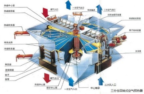
The Air Preheater absorbs waste heat from flue gas, then transfers this heat to incoming cold air by means of continuously rotating heat transfer elements of specially formed metal plates. Thousands of these high efficiency elements are spaced and compactly arranged within twenty four(or twelve) sector shaped compartments of a radially divided cylindrical shell, called the rotor. The housing surrounding the rotor is provided with duct connections at both ends, and is adequately sealed by radial and circumferential sealing members forming an primary air passage, secondary air and a gas passage through the Air Preheater.
As the rotor slowly revolves the mass of elements alternately through the gas and air passages, heat is absorbed by the element surfaces passing through the hot gas stream; then, as these same surfaces are carried through the air stream, they release the stored up heat thus greatly increasing the temperature of the incoming combustion or process air.
The air preheater furnished for this installation is designed for vertical counter flow of air and flue gases. It consists essentially of a rotor housing, hot end and cold end center sections, a rotor, heating elements, rotor seals, a rotor bearing, and a rotor drive. In this description the term “hot end “ indicates the end of the structure into which flue gases are first admitted. The term “cold end” indicated the end of the structure into which air is first admitted. The flow of air is in the opposite direction to the flow of flue gases.
2. Introduction to the structure of the air preheater
2.1 Heat exchanger elements
The heat exchange element is made of thin steel plate, and there are oblique waves on one corrugated plate, and there are straight grooves on the other piece in addition to oblique waves in different directions, and the corrugated plate with oblique waves and the positioning plate with oblique waves and straight grooves are stacked alternately. The oblique wave is at an angle of 30º with the straight groove, so that the air or flue gas flows through the heat exchange element to form a large turbulence to change the heat exchange effect. Since the cold end (i.e. flue gas outlet end and air inlet end) is most susceptible to corrosion due to temperature and combustion conditions, the heat exchanger elements are arranged in layers, where the heat exchanger elements at the hot end and the medium temperature section are made of mild steel, while the heat exchanger elements at the cold end are made of equal steel. The heat exchanger elements are housed in the element box for easy installation and removal. Among them, the heat exchange elements of the hot end and the middle temperature section are drawn vertically upward.


DU type hot end heat exchanger element NF type cold end heat exchanger element
2.1 ROTOR ASSEMBLY
The rotor assembly provides the structure for holding the heat transfer surface (heating element) within air preheater. The rotor consists of the rotor post attached with 24 diaphragms which are reinforced by stay plates arranged in concentric alignment.
The rotor post is fitted with the rotor trunnion and rotor post seal. Radial seal and T-bar assembly are mounted to the rotor diaphragms and the rotor shell.
The heating element is packed in three layers in the 24 sectors which divide the rotor evenly in the circumferential direction. The material and profile are selected to best suit the service condition.
The heating element is held in a steel container called basket. A number of basketfuls of the element are loaded in the rotor to secure a necessary extent of heating transfer surface.
All heating element is packed in baskets. The cold layer is to be removed by side removal it through the basket removal door located on the rotor housing. The hot and intermediate layer is to be removed by lifting it through upper side duct by using the provisionally installed mono rail and hoist. The baskets are reversible for extended service life.
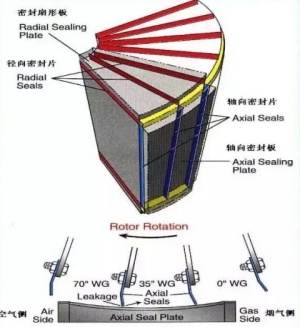
2.2 ROTOR SEALING SYSTEMS
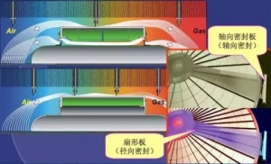
Located between the gas path and the air path, the rotor seal serves to reduce the migration of gas and air which is caused by pressure differential existing between the two flows. The sealing arrangement as a whole is made up of radial seal, rotor post, bypass seal and axial seal.
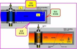
The individual seal members are set at predetermined clearance against the moving parts so that a minimum gap is retained despite the thermal distortion of those parts during operation. By reducing gas leak to a minimum, the best performance is obtained from air preheater.
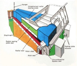
2.2.1 RADIAL SEAL
Radial sealing strips at hot and cold end of the rotor are attached to the diaphragm plates of the rotor, be capable of adjustment and forming a seal with the unrestrained sector sealing plates which are located between the gas and air apertures.
2.2.2 BY-PASS SEAL
By-pass sealing strips are attached to the rotor housing forming a seaI with a tee bar fitted to the rotor outer periphery.
2.2.3 AXIAL SEAL
Axial sealing strips attached to the rotor and positioned axially along the cylindrical shell of rotor at locations corresponding to the end of the rotor diaphragm plates and forming a seal with to adjustable axial seal plates which are attached to the inside of the main pedestal ass'y.
2.2.4 POST SEAL
Post seals are attached to the end of the rotor post forming a seal with the periphery of the rotor post.
2.3 ROTOR DRIVE UNIT
2.3.1 MAIN DRIVE
The Rotor Drive Unit is designed for continuous trouble free operation. The drive unit ships completely assembled to the drive base assembly for field mounting to the air preheater casing. This externally mounted design allows for easy access during routine inspection and maintenance.
The power train consists of an Main AC Electric motor coupled to a high-speed input shaft of a gear reducer. A pinion gear is mounted to the low speed output shaft, which engages a pin rack mounted around the circumference of the rotor shell plate.
The rotor assembly, containing the heat transfer surface (heating element), is rotated through the air and gas streams at approximately 1 RPM.
2.3.2 AUXILIARY AIR DRIVE
The rotor drive unit normally uses the main drive (AC Electric motor) to drive the rotor. It switches to the auxiliary air drive in case of emergency such as electric motor failure or loss of power supply. Switching to the air motor is automatically accomplished by solenoid valve.
The auxiliary air drive motor is also used during performance of off-load water washing or maintenance work such as heating element replacement.
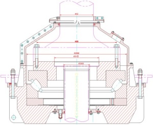
2.4 ROTOR BEARING ASSEMBLY
The rotor turns in two bearings, each called support bearing and guide bearing.
2.4.1 GUIDE BEARING ASSEMBLY
The guide bearing is installed in the bearing housing located in the upper center section of air preheater. It keeps the rotor in alignment with vertical rotational center line via the trunnion and is responsible for supporting the radial loads generated by the pressure differential between the flue gas and combustion air ducts.
The bearing assembly is lubricated by oil bath to provide continuous operation and maintains lube oil temperature at a suitable range by water-cooled lubricating oil circulating system.
2.4.2 SUPPORT BEARING ASSEMBLY
The support bearing is installed in the bearing housing located in the lower center of air preheater.It takes on the whole weight of the rotor revolving with full load of the heating element via the trunnion, as well as the radial load created by the pressure differential between the flue gas and combustion air ducts.
The support bearing assembly is lubricated by an oil bath and will be naturally cooled due to low temperature area ofair preheater support side.
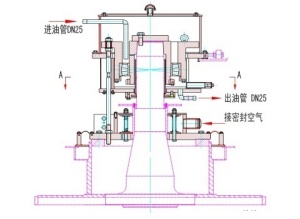
2.5 LUBE OIL CIRCULATION UNIT (FOR GUIDE BEARING)
The air preheater is furnished with a Lube Oil Circulation Unit at the guide bearings. A thermocouple is provided in guide bearing housing for control of the pump motor. The purpose of this unit is to circulate the oil for cooling when the temperature of the oil in the guide bearing housings reaches a predetermined set point. When the oil
temperature reaches the set point, the pump motor is started. After the temperature of the oil falls below the set point, the pump motor is stopped.
2.6 SOOTBLOWER
The heat transfer surface of the Air Preheater must be maintained in a deposit-free condition to attain the greatest fuel saving and highest operating efficiency. Therefore, most air preheaters serving boilers or process furnaces fired with oil or coal require equipment for online sootblowing.
To keep the heat transfer surface clean, the Air Preheater is equipped with two part retractable type sootblowers. Special attention is required to ensure that the heating element remains free of combustion deposits, particularly during start-up periods. One sootblower is located in the flue gas outlet side of the air preheater to control deposit build up on the “cold end” heating elements. An additional sootblower may be installed in the gas inlet side of the air preheater for cleaning the “hot end” heating elements.
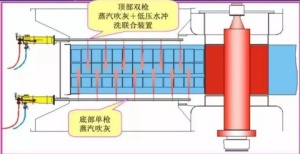
2.7 WATER WASHING DEVICE
The stationary water washing device is run when Air Preheater is shut down for regular inspection or maintenance service. It directs low-pressure water sprays at the heating surface to remove deposits that did not give in to cleaning by the blowers.
The washing device consist of two (2) stationary multi-nozzle pipes. One is located in each the gas inlet and gas outlet of the air preheater.
2.8 FIRE DETECTING SYSTEM
With its probe installed in the duct connecting to the air outlet of the Ljungstrom air preheater, this fire detection system spots fire in its incipient state and triggers fire alarm.
Fires in the air preheater result largely from the spontaneous burning of combustible deposits (soot or fuel carried over from the boiler) accumulating on the heating surface or the so-called secondary combustion in the boiler flue.
As stated, this system pinpoints a hot spot in the air preheater (abnormal temperature rise caused by the rapid oxidation of combustible deposits) which will possibly develop into a fire, or detects and monitors a fire from the early stage of development, and summons the plant personnel to an appropriate fire fighting action.
The fire detection system contributes to the improvement of the air preheater reliability by preventing a fire from causing major damage or minimizing fire-inflicted damage.
Rare as it is, air preheater fire is apt to happen during boiler start-up or light load operation. Particular care should be used during these periods.
2.9 NO ROTATION DETECTOR SYSTEM
This detector is designed to monitor electrically whether the rotor of air preheater is normally rotating and to send out a signal when the rotation is abnormal.
The device consists of a target, proximity switch and speed indication in DCS.
2.10 HOT SECTOR PLATE DRIVE UNIT
The actuator connected outward to the sector plate moves the sector plates down to the position(s) pre-set with the boiler operation control signal (boiler load and gas inlet temperature of air preheater), which results in reducing hot end radial leakage.
Contact: Mr. Liang
Phone: +86 13500015726
Tel: +86 20 87025847
Email: gzkechao@163.com
Add: Room 1605, C3 Building Wanda Plaza, No.87 Kefeng Rd., Huangpu District, Guangzhou, 510530, P.R.China